Retro computing lets you get to grips with technology’s history, showing how far modern computers have come. Here’s how to build your own working Apple I replica.
Computers have come a long way since Apple first started in 1976. In those days when Steve Jobs and Steve Wozniak first put together the original Apple I computer kits, everything was sourced and assembled by hand.
Apple was a tiny company based in Steve Jobs’ parents’ garage, and Apple sold kit computers out of the garage.
Apple I kits consisted of a huge motherboard, several dozen logic chips, large power capacitors, diodes, resistors, A ROM chip, and a 6502 CPU designed by Motorola and made by MOS Technology.
The 6502 was a common CPU in the 1980’s – being used in Apple, Atari, and Commodore computers. It was the first truly low-cost microcomputer CPU and was the key element that enabled the personal computer revolution to happen.
For the Apple I, it was also left as an exercise for the user to build a homebrew power supply and obtain a keyboard sourced from a company called Datanetics, which later made the Apple II keyboard.
You can see a 1979 photo of Jobs with an Apple II at the Computer History Museum’s website.
The Apple I was sold in kit form – no completely assembled units were sold.
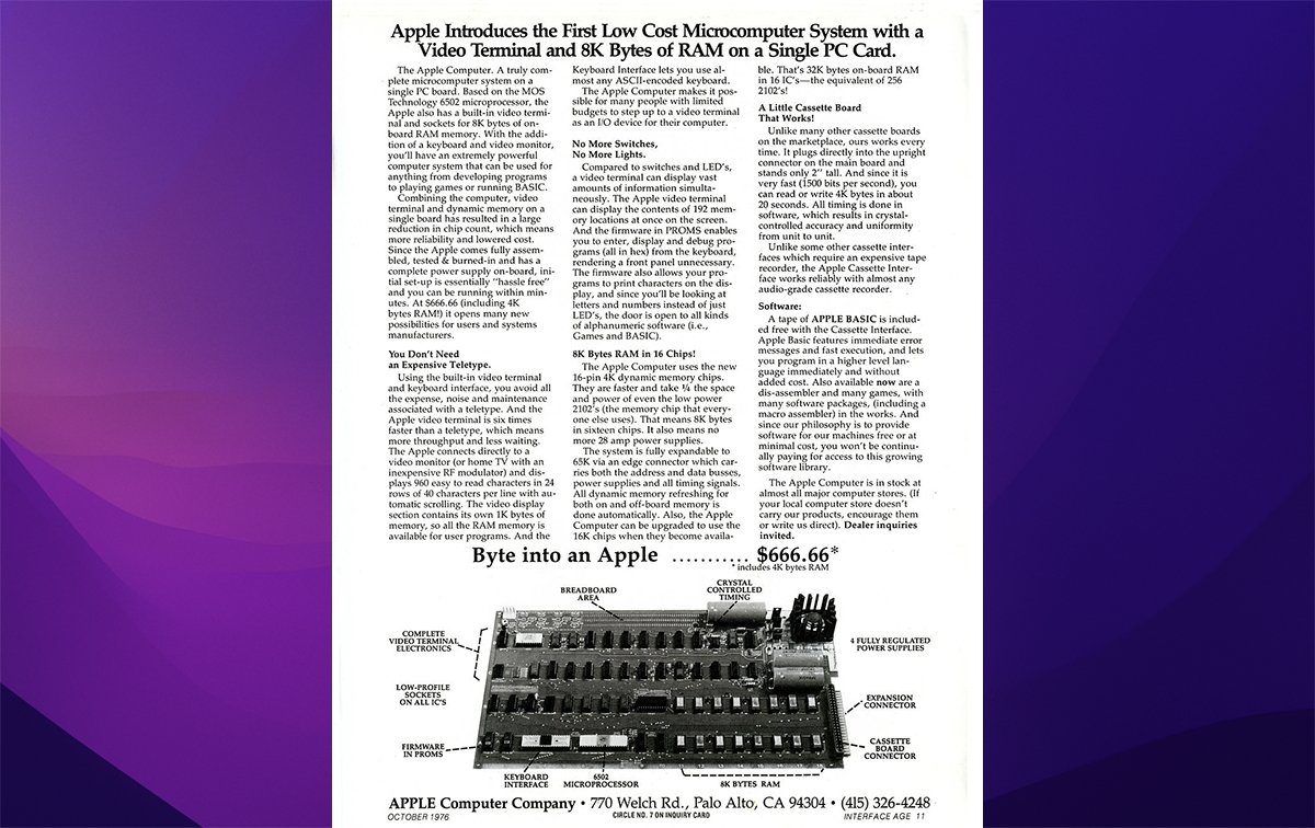
The machine was first released on April 11th, 1976 – just ten days after Apple was founded on April Fool’s day of the same year. As a joke, Steve and Steve decided to set the price of the machine at $666.66 US dollars.
The Apple I’s sales were small, mainly due to its extremely limited capabilities. There were also much more advanced kits from other companies available, such as Sinclair of the UK, whose machines offered built-in video, graphics, a keyboard, a cassette port, and later, color.
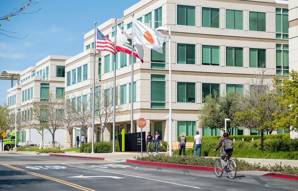
Steve Wozniak’s original Apple I computer, built in the Jobs family garage and housed in a wooden box, was originally on display at Apple’s own internal museum at R+D Six on 1 Infinite Loop, in Cupertino, CA, but it now sits in the Smithsonian Museum in Washington, DC.
The follow-up computer, the Apple II, shipped two years later in a fully assembled case, complete with internal power supply and keyboard. It included a graphics mode and supported BASIC, which had to be loaded from floppy disk, or a ROM-based add-in card.
A second model, the Apple II+ a year later supported built-in BASIC, and booting from an external floppy disk.
The Apple II was Apple’s first killer product, and when the Apple II’s first killer app VisiCalc was written by Dan Bricklin and Bob Frankston a year later, Apple became Silicon Valley’s first hit billion-dollar personal computer company overnight.
Apple II computers flew off the shelves as accountants and other business people used VisiCalc to manage their businesses and automate bookkeeping and forecasting.
The Apple I was severely limited, mainly because RAM was extremely expensive at the time, and the machine supported 4K or 8K of RAM expandable to 32K. The Apple I was text-only, and lacked a graphics mode, color, and sprites for game creation.
The machine had no operating system – BASIC could be loaded from an optional Compact Cassette, a popular audio format of the 1970s, provided the user also built the optional cassette expansion interface card which fit the machine’s single expansion port.
Without BASIC, if the user wanted to program the Apple I they had to use Motorola 6502 assembly language and the machine’s built-in monitor, WozMon.
Fast-forward forty-five years
In today’s world, printed circuit boards (PCBs) can be designed in hours or days in software, the file saved and uploaded over the internet to PCB production houses all over the world. The purchaser can have boards at their door within a week – almost for no cost.
Combine this with modern advances in processors and microcontrollers such as FPGAs, flash EPROMS, and IoT devices such as Arduino, and you have all the makings of a new retro computing revolution.
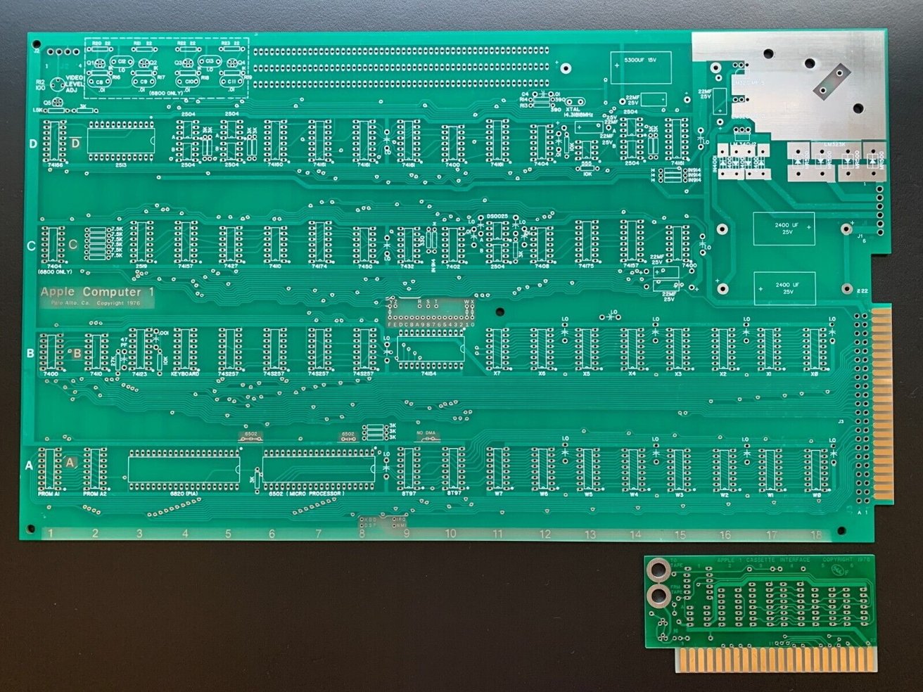
Several enterprising entrepreneurs have recreated the original Apple I PCB and now sell them online including on eBay and Etsy. You can purchase one of these boards and repopulate them yourself with parts, building a brand new working exact replica of the original Apple I.
You’ll need to also find an original working Apple I ROM chip, and build your own custom power supply for the board or find one prebuilt online. The Apple I’s original documentation can also be located online, but be aware the document is still copyrighted material owned by Apple, Inc.
A replica Apple I PCB for sale on eBay from seller “newton-computer”. The cassette interface PCB is also included.
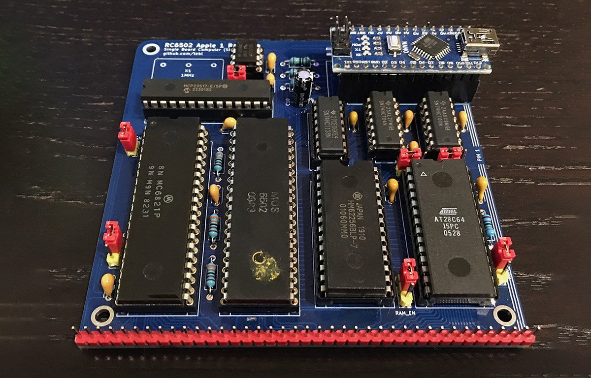
RC6502 replica PCB
If you’re not up to the task of buying and assembling everything needed to make a new original Apple I, there’s a better way. Tebi of Norway has created a tiny new PCB called RC6502 which uses the original Apple I ROM, a single SRAM chip, a 6502 CPU running at 1MHz, and a single 6821P PIA chip, also originally made by Motorola.
The board also requires a single Arduino Nano, which you have to load a program into, as well as a few other small components. You can also make an optional backplane PCB to add other features including a video display unit.
The RC6502 is open source, and you can download the Gerber files and order your own online, or order a board from sellers on eBay, Amazon, Etsy, and a host of other online outlets. A Gerber file is a computer-generated schematic of an electronic circuit that is used to produce a PCB.
The big advantage of the RC6502 is its size and low component count, as the total cost to build the board is under $50.
Getting started
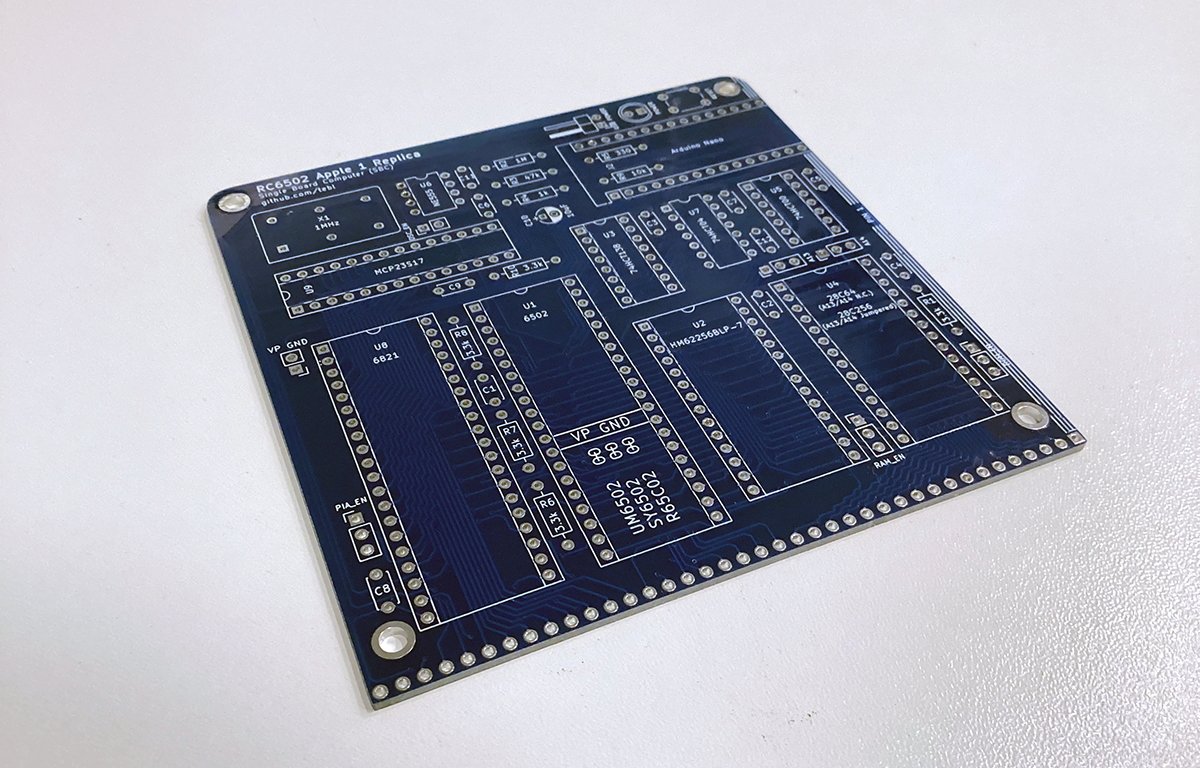
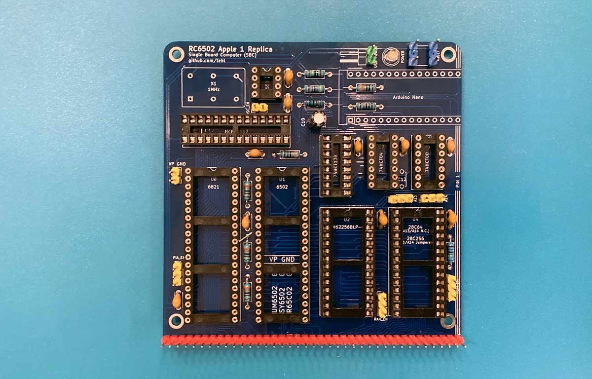
Let’s take a look at the bare PCB:
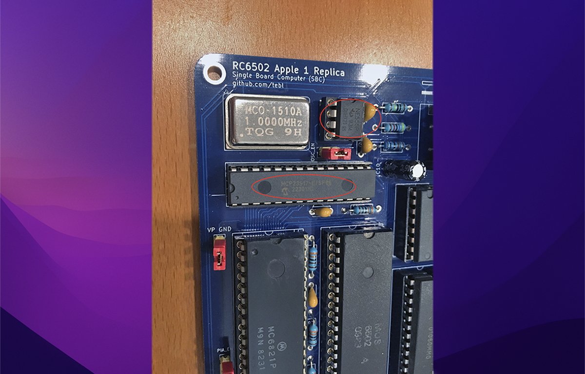
In the upper left corner, there are 3 components: a 1MHz crystal oscillator chip, a common 555 timer chip, and an MCP23S17-E/SP Serial Peripheral Interface (SPI) chip. The last one, made by Microchip Technology Inc. of Chandler, AZ, helps the board communicate with an Arduino Nano.
The MCP23S17-E/SP can be a bit expensive and difficult to find due to supply chain issues caused by the COVID pandemic, but they are slowly becoming more available.
DigiKey seems to have a huge stock now, or try AliExpress. We found ours on AliExpress, but it cost $7 including shipping during the shortage.
In the upper right corner of the board is a space for Arduino Nano headers, which you must solder in so you can plug an Arduino into them.
Below that are 3 common logic chips: 74HCT138N, 74HCT04N, and 74HCT00N. These are logic gates, multiplexers, and inverters and all cost around a few dollars each.
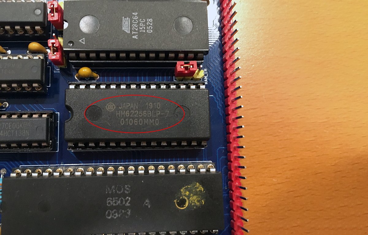
Under the three logic chips are a single SRAM chip (HM62256BLP-7 made by Hitachi, or an equivalent), and a single flashable EPROM, in this case an Atmel AT28C64-15PC). You’ll also need a USB programmer device to flash the Atmel chip.
The “-7” at the end of the HM62256BLP-7 indicates the RAM speed – in this case 70ns, but you may be able to get slightly slower chips to work, possibly as slow as 100ns (or “-10” at the end of the chip model name). In most cases, if the speed is close, the RAM can be slowed down to match the board speed.
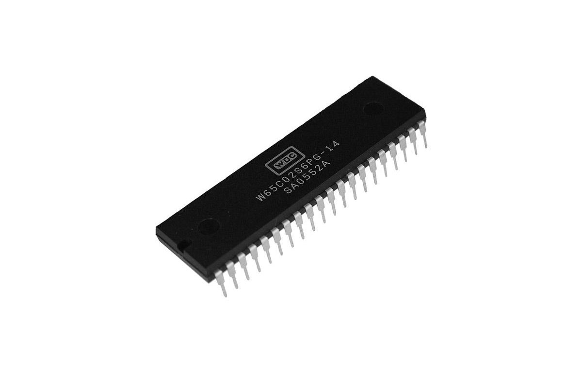
To the left of the RAM and EPROM is a Motorola 6502 CPU, running at 1 MHz, although you may be able to get the 6502’s modern equivalent, the 65C02 to work also. 65C02 is a modern replacement for the 6502, and is made by Western Design Center (the successor company to MOS Technology), located in Mesa, AZ.
The 65C02 uses a more modern design, uses less than 1/10th the power of the original 6502s, and can be run at variable speed up to 14MHz. Pin 37 is a clock input pin so the CPU can be driven by an external oscillator – in this case the 1MHz crystal.
If you don’t use a 65C02, you’ll need to source a working used 6502, or a New Old Stock one from online sellers. They can be found on eBay, sometimes on Amazon, on AliExpress, or a host of other overseas sellers.
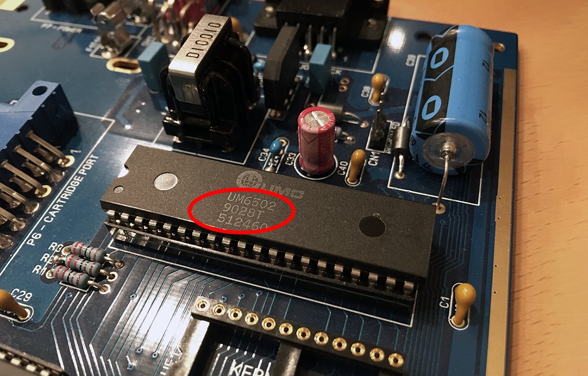
While Motorola made the original 6502, they were later licensed to MOS so you may see 6502 models from both companies. The 6502 was also later licensed to Rockwell International and UMC.
You can still find NOS Rockwell and UMC 6502’s which are decades old but have never been used.
Usually, chips have a date stamp code on them with the week, month, and year they were manufactured. The year is typically listed first in the date code – but not always.
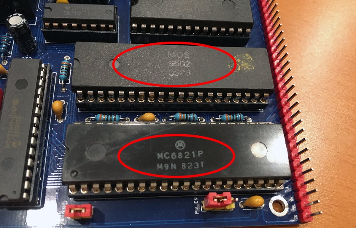
In the photo below, the 6502 date stamp code is “0988” – indicating September, 1988.
In most cases, it’s generally better to get the newest chips possible as some early production runs may have had problems, and in most cases, chips’ materials degrade over time. So a chip made in 1992 would be generally better than one made in 1979.
Usually, genuine Motorola 6502s have the Motorola “M” logo on them, but not always. Some chips end up as e-waste in China or India and are pulled from boards, refurbished, and resurfaced, usually with a generic print on them, such as the one shown above.
Be aware that some chips from China are fake and while they may work, they may not be reliable or work for long.
You will also need some IC sockets, jumper headers, PC motherboard-style plastic jumpers, various resistors, and ceramic capacitors – mostly, but not all 104’s or 0.1uF.
For a full list of the Bill of Materials (BOM) for the project, see Tebi’s GitHub page.
Solder sockets and basic parts
First you’ll want to solder in all resistors, ceramic capacitors, the one electrolytic capacitor, one small momentary-on push button switch, and the jumper headers. Take your time and verify all solder joints.
There are two types of IC sockets: one kind (the cheaper kind) has flat leaf-like connections and a plastic surround which sits flat against the PCB.
While less expensive, these are also less reliable: the small metal leaves that hold IC pins can get dislocated, and it’s impossible to see under the plastic housing since it sits flush.
The other kind of socket uses rounded raised pins, with round holes on top, and is often gold-plated to prevent corrosion – even decades into the future. The second type of socket costs a little more but is well worth it.
They also allow you to inspect the top side of solder joints on a PCB to ensure there are no unwanted bridges between holes (known as vias).
Note that sockets and ICs usually have a semi-circle-shaped notch on one end. Usually, PCBs also have markings with a semi-circle notch. Solder sockets in so the notches match the PCB markings.
The notches ensure ICs get inserted the correct way matching the sockets. This prevents fried chips due to backward insertion.
You’ll also need to solder on the tiny reset switch, or headers for an external switch, power, and power LED in the upper-right corner of the board.
The long pin header along the bottom of the board has a variety of connections, including power and other features. See the GitHub page and documentation for a complete pinout of all the long jumper pins.
An initial build with all small components installed looks like this:
Install chips
Next, solder in two rows of pin socket headers for the Arduino Nano in the upper-right corner of the board, and install all chips in their sockets except the Atmel EPROM chip.
EPROM means Erasable Programmable Read Only Memory. You’ll need to use a USB programmer device on a PC to flash the EPROM chip.
Once flashed, insert the Atmel chip in its socket. Also, solder in the 1Mhz crystal in the upper left corner of the board.
Be very careful when inserting ICs into their sockets to insure no pins get bent or miss the socket holes.
Next, add small plastic jumpers to the jumper pins as described in the documentation. There are jumpers for RAM amount, PIA-enable, ROM-enable, and others. Each jumper setting modifies how the board behaves.
Backplane and optional video
An earlier version of the RC6502 Apple I used a backplane board, which you can still build, and several daughter cards which the jumpers enabled or disabled. But the newer version of the board is a Single Board Computer (SBC) design which is self-contained.
If you want to use the backplane board, you’ll need to use an angled header on the SBC for the long header connector so that the board can be plugged in vertically into the backplane.
If you want to use an actual video display with the board, you’ll need to add two small, additional boards (called Video Display Units), and the backplane board. If not, then you’ll connect to the SBC board over a serial connection via the Arduino.
See the Bus.md document on the GitHub page for a full description of the system bus and pinout.
Power
If you want to power the board using the Arduino’s USB connection, and you’re not using the backplane, add a jumper to the two-pin header just next to the power LED marked “USB Power”.
If not, the backplane supplies power from its DC power jack on pins 17 and 18 of the long header on the SBC. For the Arduino USB connection, you may want to get a USB cable with a power switch on it so you can turn the power on and off.
Once everything is ready connect the Arduino USB cable, plug it into your Mac, and throw the power switch.
Arduino connection
Once powered on, you’ll need to launch the Arduino IDE app on your Mac or PC and under Tools->Boards->Arduino AVR Boards select Arduino Nano. Once selected you may also need to set the serial port under Tools->Port if it doesn’t select automatically.
Once connected in the Arduino IDE, upload the PIA Communicator sketch program to the Arduino using the IDE as mentioned in the documentation. This lets the IDE’s serial monitor communicate with the Apple I and display its output in a window on your Mac.
If you have trouble connecting, check the baud rate – the rate at which data is transferred across the serial connection. It should be set to 115200.
If everything works as planned, in the serial monitor in the Arduino IDE you should see a single exclamation point: “!”. You can now type in any hexadecimal address to display its contents.
PIA Communicator also lets you upload both 6502 assembly and BASIC programs to the Apple I and run them. Once you have BASIC loaded on the Apple I you can type BASIC programs directly into the Apple I over the serial connection and run them.
BASIC switches the command line prompt to display a “>” instead of the “!” in the serial window.
Built-in apps
Three apps are built into the Apple I ROM. These are listed on the back of the RC6502 PCB under the CPU, along with the ROM memory addresses in hexadecimal you need to access them. These are:
- Integer BASIC (E000)
- Krusader Assembler (F000)
- Woz Monitor (FF00)
To run any of the three programs, at the “!” prompt type the hex address, followed by a space, then a capital “R”, then press Return. For example, to load Integer BASIC on the Apple I from the Arduino serial window on your Mac type:
You should see the serial window prompt change to: “>”.
You’re now in BASIC and can type in BASIC programs. Once a BASIC program is entered, type run and press Return to run it.
The world of retro computing is expanding and the RC6502 is a quick and inexpensive way to get started with an Apple I build.
Also be sure to check out Tom Owad’s remarkable book Apple I Replica Creation: Back to the Garage ($6 PDF) – which contains an introduction by Steve Wozniak himself.
This story originally appeared on Appleinsider


